Created July 3, 2002
Updated January 15, 2003
I have been building various VCOs now since 1974. Some have been succesful, some have been failures, some right in between. The Curtis CEM3340, of course, is pretty much acknowledged as one of the best VCOs ever made, but alas, that chip is not really availiable any longer, and when you do find one, it is very expensive.
The main problem with VCOs that use an exponential conveter, which is what gives you the 1 volt/octave scaling, is that they are very temperature sensitive. They have two major drift components, offset and scale. Offset drift, while annoying, can be delt with fairly easily. Scale drift cannot. The scale drift of an uncompensated exponential converter is about -3300ppM/C. To compensate for this, most designs use a so called Tempco Resistor. One of the best known ones was the Tel Labs Q81 type resistor. I actually have some of these for sale on my web site, but, because they are imposible to get these days, they are expensive and should only be used to refurbish old equipment. Other Tempco alternatives do exist. However, you will find that they are still somewhat pricey. And also, difficult to locate.
Building a temperature compensated exponential converter has been the holy grail for myself, and others, and several designs have popped up from time to time. There are three basic catagories to solve this problem. First there is Temperature Control, second is Passive, and third is Active.
Temperature Control
One of the popular ones is temperature control. By using a transistor array with at least 4 transistors in it, you can create a heater/sensor pair that is used to control the temperature at an elevated level. This has the advantage that it is relatively simple. The number of parts it adds is minimal. The disadvantage is that it will reduce the scale drift only by the loop gain of the temperature controller. Although, for all practical purposes, it will reduce the scale drift down into the mud, or in other words, there will be other things that affect the scale drift more. Another disadvantage is that this consumes a lot of power, and it has a limited temperature range over which it can operate. Obviously, there is a maximum temperature past which the loop can no longer control the temperature. You can set the control temperature really high, but, this takes more power. There is a minimum temperature below which there won't be enough power to heat the chip up to its operating temperature. This can be solved by using insulation, but this will also affect the loop dynamics.
Passive Compensation
This is the most common methode. This can be done with a tempco resistor, as described above. You can also use the gain of an OTA. The gain of an OTA has the same -3300ppM/C tempco that the expo pair has. Paia uses this methode to compensate their 9720 oscilator. The disadvantage is that an OTA is not a very linear amplifier, plus, you really need to glue the expo pair to the LM13700 they use to make sure that they track correctly. I define passive compensation as any compensation where the temperature is used to directly control the gain of the compensating element. There is nothing wrong with this, but care must be taken to make sure that the expo pair and the compensating element are at the same temperature. Passive Compensation has the very distinct advantage of using the fewest number of parts.
Active Compensation
Now we come to the most complicated scheme. Active compensation differs from passive in that we measure the temperature of the exponential pair and create a voltage that will change with temperature. If we use a semiconductor junction to do this, we will get the most convienient 3300ppM/C change in voltage. We then use that voltage to control the gain of a VCA such that as temperature rises, the gain of the VCA increases. The VCA was probably the most difficult task. I have used 4 quadrant multipliers, which were, eh, OK, but these parts are very expensive ($6 if you are lucky). I also made a two quadrant gilbert multiplier using a CA3046 and a LM13700 which worked OK. The problem was is that this used a lot of parts. The VCA I am using right now is made from both halves of an LM13700. See the schematic below for details. The connection I use gets me good linearity, temperature stability, and low cost. There are still the extra components needed to control the gain of the VCA, but the parts count is not outrageous.
There are several other people who have experimented with Active Compensation as well. And their work was a great help to me in coming up with my own circuits. There names will be listed in this line as soon as I look them up on the web and get their names spelt correctly.
The Circuit
This description has been updated...the original circuit was pretty
bogus.
Most of the action takes place on page 3. This is the VCO core and exponential converter. The actual oscilator is really nothing of interest. It is the same old tried and true oscilator that many synthesizer enthusiasts use. The exponential converter, on the other hand, is a little different (not much however).
U6A is just a standard summing amplifier. Its output goes into the VCA. The VCA is made out of U9a and U9b. U9a is used to linearize the VCA. This also provides temperature compensation for the gain of the VCA so that is has basically zero TC. One thing you should note about the circuit. As Iabc for U9a increases, the overall gain of the VCA decreases. As Iabc for U9b increases, the overall gain of the VCA increases. This is a very handy property for what needs to be done.
The output of U9b goes to the base, pin 2, of Q6a.
As the voltage on the base Q6a increases, collector current will increase
exponentially. But, there is a lot more to the exponential converter
than just that. The base emmiter junction of Q6a from pin 3 to pin
4, U10, and U11b form the part of the circuit that measures the temperature
of the transistor die. As the temperature of Q6 increases,
the Base-Emmitter voltage between pins 3 and 4 will decrease. U11b
generates a constant current based on this voltage, so as the temperature
increases, the current form Q7 will decrease. This current controls
the gain of U9a, which will increase the gain of the VCA (this is
a positive tempco in gain, which is what we need).
Schematic Diagram of Panel Mount VCO
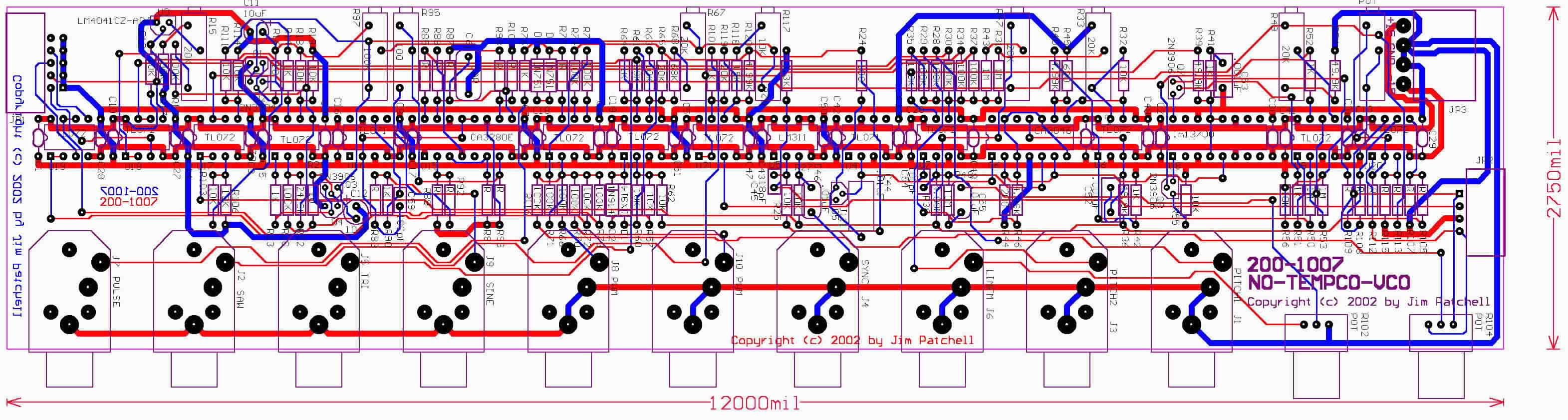
Picture of Panel Mount VCO PC Board Layout
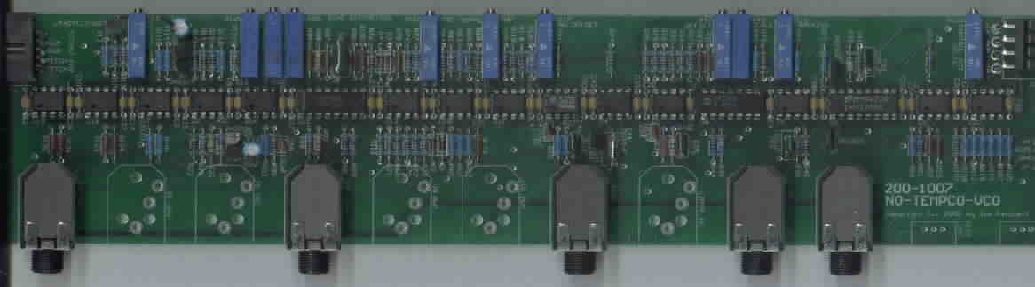
Photograph of Prototype VCO (incomplete)