This projects was inspired by Gene Stopp's ASM-1. It will incorporate my own module designs but basically will cover the same functionality. I would just build Gene's board, but that is not what I want to do.
The only module that I will have to do any major work on will be the VCO's. The last VCO's I did used the CEM3340, which makes them a no brainer since this chip performed so well. I am attempting to come up with a new approach to designing an exponential converter that will hopefully approach the performance of the CEM3340 chip. But that is going to take a while. Once the breadboard is constructed, it will take quite a bit of testing to determine if it has good scale stability. I am attempting to come up with a method that does not involve temperature controllers. There is nothing wrong with temperature controllers, but this generally requires a transistor array with four transistors in it. If I am successful with my new idea, this method will work even with dual transistor pairs.
Right now, the synth module board is planned to have the following modules:
VCO
4
MultiMode
VCF
1
24db/oct
LPVCF
1
ADSR
2
ASR
2
VCLFO
2
VCA
2
SCALE/INVERT
4
VC4in1out MIXER 1
4 in 1 out CV Mixer 2
Noise
Generator
1
GLIDE
2
Voltage
Scaner
4
Sample/Hold
1
Midi Interface:In,Out,Thru,4 control voltages,
gate, trigger, midi clock
Built In digital sequencer:4 CV out, 4 Gates
A bit ambitious, I know, but I like high goals. Some of the features are:
VCO-Saw,PWM outs, sync, 1V/oct, Lin FM, PW inputs
MultiMode VCF- LP,BP,HP outputs, 1V/oct Frequency,
Linear Q inputs
24db/oct LPVCF - Implemented like a SSM2040 (sorry
not a ladder), LP output, 1V/oct frequency, Res Control
ADSR-Voltage Controlled ADSR-Adjustable
Exponential->Linear
Waveforms
VCLFO-Triangle, Square outputs, 1V/oct freq
VCA-Linear Control Response, nothing special
SCALE/INVERT/Ballanced Modulator-Scale(attenuator),
invert (Same Control as attenuator), Balanced Mod- based on AD633
multiplier,
nothing special.
4in/1out Mixer-Yep, summing amplifier
NOISE-White,Pink, Low Frequency, generated with
semiconductor junction.
GLIDE-Adjustable from exponential to linear glide.
There will be more details as the designs are finished.
Availability: once released, all circuits will be in the public domain. You can use them, you can build them, or you can ignore them, for free. The ultimate goal is to fab a printed wiring board. If there is any interest, I will make it available for a nominal fee, or, you will be able to download the gerber and drill files and have them built yourself.
At one point I was considering producing this board. But, hey, it took me 4 years to complete this. And I knew exactly what I was doing. I don't think it would be posible for me to support this board.
Latest News 12-01-2002
Well, it has been almost 4 years since this web page went up, and the SMB board is finally getting close to being finished. Today, I finally got the Midi code written for the AVR that goes on the board. As of this moment, the status of the code is that it functions, I still have to iron out the logic on how the Gate works when you press a new note. Right now, there really isn't any. The main problem I had was in setting up the Image Craft Compiler for the 8515. When I originally got the compiler about 2 years ago, I had figured this out fairly quickly, but, hey, I forgot. When I created the project for the midi code, I forgot to set the processor to 8515 and thus had some rather strange things happening. Still, all in all, it only took me about a week in real time to get the code in the state it is as of today.
Lateset News 8-06-2002
It has been a while since I have posted any news about this project. Many things have happened in the last year since I last updated this webpage. The ecconomic downturn has had a severe impact on my projects since I no longer have an assured income string. The company I worked for shut down the division I was in on April 5, 2002. The job I have right now is on shakey ground. Still....
I just finished tuning the VCO's. While they do work pretty good, this design is fairly "old" now. The one problem I have noted is that the oscilators are not as linear as I hoped. They track to within about 20 cents over 6 octaves. This seems to be due to the fact that the LM13700/LM3046 gilbert multiplier that I concocted is only linear to perhaps about 0.2 -> 0.4%, which is what you would expect from this circuit anyway. And is also what I feared when I designed it. Back when I designed it I didn't really have the equipment to accurately measure the pitch. Else where on this web page is a much better multiplier circuit that use in my current VCO designs (see the 200-1007), which on the breadboard version was tracking to withing a few cents over 9 octaves.
Hopefully, in a couple of weeks, I will be posting some MP3 files that demo this synth being used with the Mikado Analog Sequencer.
Latest News 7-20-2000
I just got the PC boards back from the fab house. I ordered 2, got three, one of them is a scrap board that, while not great, may prove usefull. I will now be starting the long task of assembling this board. I still have quite a few parts that need to be purchased.
Other tasks that need to be completed is the purchase of a C compiler for the AVR. I still haven't made up my mind yet.
Latest News as of
8-4-2000
I have most of the resistors
mounted on the board. I am still lacking certain values, and as
soon
as I can aford them, they will be ordered. I am also assembling
the
front panel. I ran out of 1/4" switchcraft jacks and will have to
order some more of these as well. This project is really eating
up
my resources. Don't be fooled, building something like this
yourself
is very expensive. I already have about $1200 sunk into it, and I
am not even close yet to having the first one done.
Latest News as of 8-17-2001
Well, this sure has been one hell of a project. And it still isn't done yet. All of the modules, except the Midi->CV converter have been tested, and they are all functional. There are going to be some minor revisions. I am changing the circiut in the ADSR generator a little bit. The logic that I originally did has a minor quirk, i.e. one works, the other has a small glitch in it. I am making the circuit similar to the voltage controlled ADSR board I am doing. The other rev is in the scanner modules. Because of the way I did the circuit, the waveform is not quite perfect. I am rearranging the component a bit to fix this.
SMB-1 schematic updated 8-13-2000
Printed Circuit Board Layout (preliminary)
Front Panel Layout
(preliminary)
Final Entry for this Blog...well...perhaps...9-4-2005
Well, I think I can consider this project DONE!
Final conclusions...
I will never ever be making a PC board that big
again. I can probably better deal with it now...but splitting the
project into smaller boards seems to work a lot better. Also,
many of the construction techniques I used on this system I would
consider to now be "obsolete". Running cables to the front panel
is a real drag. I still have one huge project yet where I am
committed to do this...oh well.
The only "bug" in the hard ware would be the
temperture compensation used on the VCO's. The still drift by 400
ppM in this one. I would like to fix that...but there seems to be
no clean way to do that...unless I redo the board (very unlikely).
The Modules
VCO's
ADSR
SCANNER
ASR
Low Pass Four Pole Filter
This fileter is a "clone" of the Solid State Music SSM2040 filter IC. This part has long ago not been made. My version of it has been implemented using four THAT140 transistor arrays. The low pass circuit itself comes right off of the SSM2040 data sheet. The circuit for the OTA came from an article that appeared in the September 13, 1976 Electronic Design Magazine by Dr Sergio Franco. It should be pretty much just like the original in performance. Hopefully, it will prove also to be quiet.
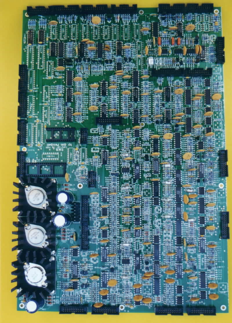
Multimode Filter
This is a picture of the printed circuit board. This is how the board stood as of 11-25-2000. Still not complete. One more round of ordering parts, and it should be done.
This is a picture of the front panel. Now, if you downloaded the gerber file of the front panel, you will notice it is not the same. That is because for the first one, I did not want to have to pay to get silk screening done. So, I painted it and lettered it by hand.
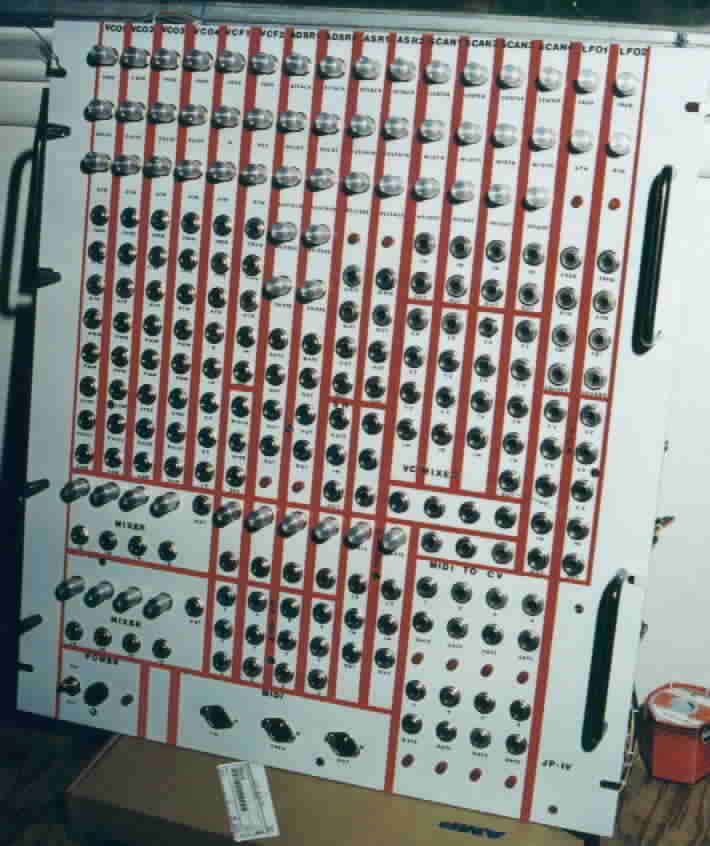
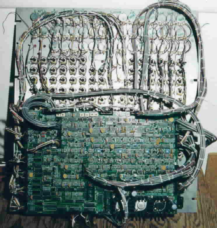
The picture above is the panel completely
assembled,
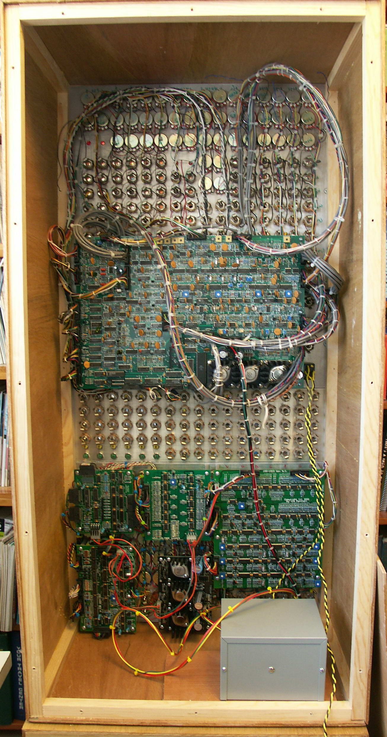
including handles. Below, you see the rear of the front
panel.
The wiring is pretty much finished. I am not sure how long it
took
me to do the wiring, but is was several months. This below
picture
was taken April 29, 2001. The wiring did not turn out as nicely
as
I had hoped. I am trying to find much nicer shielded cable.
The stuff I used, while the lightest I could find, was way to
heavy.
The next step is to power it up.
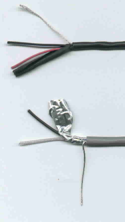
Below you find images of two types of shielded cable. The one on top will be what I will use for my next synth project. Below it, you see a picture of the cable that was used to wire the above picture. Both cables have two wires, an aluminum foil shield, a drain wire, and a PVC outer jacket. The black cable also has an aditional inner jacket as well. The black cable is more flexible and a slightly smaller diameter. Also, it uses 24ga wire, instead of the 22ga of the grey cable. Also, the wires in the black cable are much easier to strip with my Ideal Custom Stripmaster wire strippers. The part number for the black cable is C1228-1000 from Digikey.
Bill of Materials
7-04-2000
Temperature Compensation of Exponential Converters
This is a subject that has bothered me for a long time. I am now starting to work on ways that this can be done with easy to purchase components. A tall order. But I know it can be done. The CEM3340 is a prime example. The tempco in that part is electronically compensated, as opposed to using temperature control or thermistors. Temperature control is of course an option, but if you use a MAT02 or MAT03 for the log transistor, it is difficult to do.
Right now the plan is like this.
Temperature Sensor. This is the easy part. In an exponential converter that uses a pair of transistors, one transistor has a constant current running through it. This means that the base emitter junction has a constant current. When a constant current flows through a forward biased junction, the voltage is proportional to the temperature.
Gain Control Element. This is a little tougher. For things like voltage controlled filters, a little non-linearity in the frequency scale is not going to be noticed. However, for a voltage controlled oscillator, it will. The non-linearity for an AD633 on the Y input is 0.2%. This is significant. I am still going to build up a bread board and find out just how bad it is. Other alternatives is to possibly use an LM13600/700 with a gilbert front end, although, this will require another set of matched transistors. This may or may not perform better than the AD633. The only other thing that will be needed to do is calculate the gain from the temp sensor to get the correct tempco. For things that don't require great linearity, probably just half of a CA3280 or LM13600/700 will do the trick.
Results: 5-22-2000
It appears that I was successful in contructing electronic temperature compensation. I tested out the circuit on a triangle oscilator that I am working on. This is not the same oscilator that is going to be used on the Synth Module Board, but that should not matter. The results were pretty good. The triangle oscilator is showing about 390ppM/C scale drift. I will be doing more tests, and I am going to breadboard up a sawtooth oscilator. I am not sure, but I suspect that the triangle oscilator current switch is contributing to the drift.
It should be noted that is was a suggestion by Jürgen Haible that led me down the path of using the diode current of the linearizer in the OTA for controlling the gain for temperature compsation. For this, I that him.
Oscillator Design
Today is 12/19/98. I have been following the goings on the D.I.Y. Synth List Server. Recent discussion has centered on capacitor discharge. One idea that has come up is to have a set of analog switches that just reverse the capacitor in the integrator, thus avoiding having to actually discharge it. Very clever. I cannot remember who it was that first mentioned this, but he gets the credit, not me. Some of the problems that have yet to be solved are how to hard sync this oscillator. Some of the nifty features are you can get a triangle wave that is one half of the saw tooth frequency. Cool.
I have a few ideas of my
own
that are a little more traditional that I am working on. But one
of the features I want is a hard sync that will set the output voltage
to a true zero volts. At least for the sawtooth. Don't know
if this will really buy me anything but I won't know until I try it.
Sub Octave Divider
I am working on a sub
octave
divider that will take a sawtooth wave and produce a sawtooth that is
1/2
the frequency. Not really sure if such a thing is usefull.
I have never used a sub octave divider before, but when I thought up
this
idea it will be something that I will have to try.
How about a Gilbert front end ota? Fairly easy to make from an LM13700 and a CA3046. This has not been tested yet, but at this point don't see any major problems. The diode bias point needs to be tied to a voltage sourse. It must be higher than the largest signal you are going, but withing the common mode input range of the 13700.
By the way, last time I was
on the National Semiconductor Web page, the LM13600 was listed as being
a life time buy. The LM13700 is still availiable.