Strobe Tuner
Webpage
First Posted
Updated August 21, 2008
This is the simplest of the strobe tuners I am doing. This one, is in fact, a real strobe tuner. And you will probably notice that there are indeed no moving parts in this thing, so you may well ask how is it a strobe tuner.
If you look on page four of the schematic you will see the circuit for the phase accumulator that provides the reference frequency for the strobe. Phase accumulator is just a fancy way of saying counter. It is a special counter in that the counter will increment by the value that is place in the frequency register (U8, U11, U16). The output of the phase accumulator, or rather, the upper five bits, go to a decoder that will decode the 5 bits into one of 32 outputs. Each output will then select one of 32 LEDs that are arranged in a circle.
Now on page 5 is the analog input circuitry that interfaces between a microphone and the circuit that generate a constant current. The output of the constant current source is connected to all 32 LEDs. Now what happens is if there is enough current generated to light the leds, the one that will light is the one selected by the current value that is in the phase accumulator. If the frequency that is being generated by the phase accumulator matches the frequency of the input signal, you will see a pattern in the LEDs that will appear to stand still. If the frequencies differ by say 1Hz, you will see the pattern rotate in one direction 1 revolution per second.
Feb 6, 2005
Just to let you know that something is
being done on this, I did do a bit of work on the PC board layout this
weekend. I am hoping to finish this up by the end of the
week. It is going to be a fairly good size printed circuit card,
but it should be fairly quick to route as the circuit density is fairly
low. I will keep you posted, if you happen to be watching this
page...
Feb 9, 2005
Well, I finally got some work done on this thing. I just completed routing the PC Board. It is 10 x 6 inches which just gets me within the constraints of being able to get the boards made for $33 each at Advanced circuits. I still have a few little details that I need to take care of before I send it out...like the AGC loop has positive feedback instead of negative, there are two 74HC14's on the board with only one gate used, and a few other things. I should be able to get this out by Friday. It is about time...I have been working on this off and on for 10+ years.
PC Board layout (pdf)
Feb 26, 2005
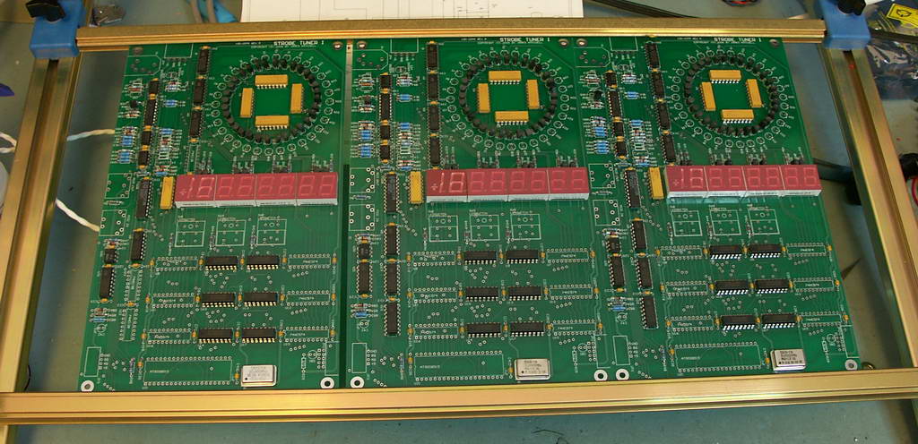
Well, yesterday the PC boards arrived, and I have started to stuff them. I am missing a few parts, the most important one is the 74HC574. I thought I had some of these lying around the house, but, I was wrong. So, I will have to order some of those. I would say the board at least looks real nice. I just hope this thing actually works. Click on the thumb nail below to see the three boards I got mounted in my assembly frame. The LED's will have to wait for me to make a jig so they can be soldered into the board in exactly the right position. I am still trying to decide on Blue, Red, Yellow or Green LEDs.
Strobe Tuner II
Strobe tuner II is going to be different in that the circuit will be able to process the in coming signal and tell you how far out of tune it is. It will also be able to communicate with a host computer so that data can be logged. This is being designed mostly for use in tuning the VCO’s in my Synthesizers. There is more to come on this later. I want to get the first one working first, since many of the ideas in I are also going to be needed in II.