Synth Module Board - Cheezy Version
SMBC
First Posted Jan 17, 2012
Updated October 29, 2018
It has been a long time since I had the idea of
making a Cheezy Synth board. It never happened because at the
time I did not want to pay close to $400 to get a small set of boards
made and also because at the time I felt that my blindness would
prevent me from building the board. But I have a lot more
confidence in myself now, so I am revisiting this project.
However, since that time I have changed computers. I am now
runnning Windows 10, which will not allow me to use Protel version 2.7
any longer, so I am starting over using KiCad, which is better because
it is in the public domain. Also, I decided to make the cheezy
boad a little less cheezy. It will sport an ATmega1284 (128K
flash, 16K ram) processor as well as a state variable filter and my new
Blackmer VCA. It will still have the cheezy drum circuits that
were designed by John Simonton.
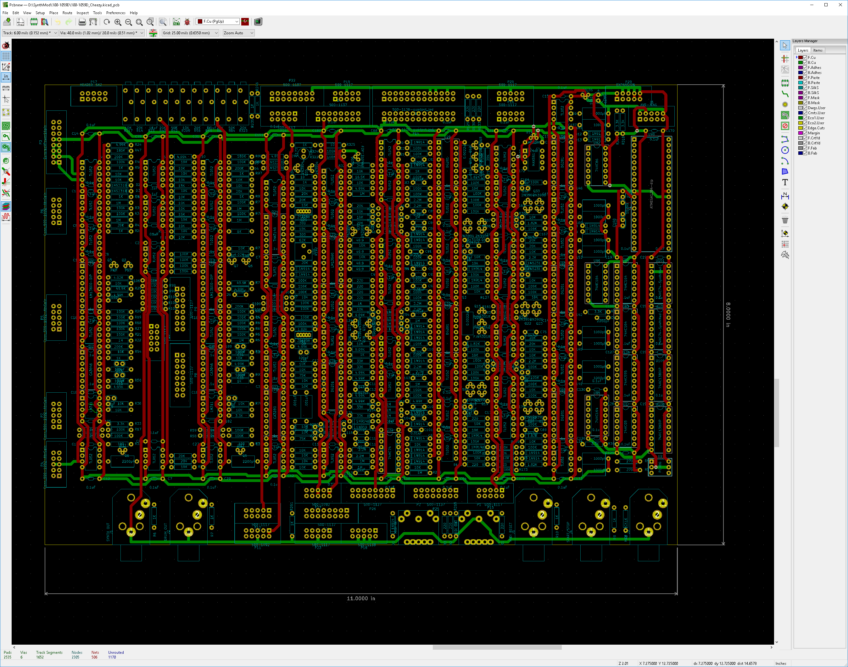
And this is what the PC Board will look like.
Back in October 2014:
It has been a while since I have done a synth project. I am
taking a crack at making a fairly simple synthesizer module board.
My main goal here is to keep the parts count low. The only
part that I am not going to compromise much on is the VCO. But,
the rest, I am going to try and be as minimalizst as I can. And,
in a way, I am going to be doing a blast from the past, in some
ways. The first synthesizer filter I ever built and used
was the PAiA 2720 band pass filter. This filter used a twin T
notch filter in a feed back loop of a transistor amplifier to make a
band pass filter. It was tuned with a single diode in one of the
T networks.. Well, I am going to do something similar.
Rather than use a diode to tune the thing, I thought I would try
an OTA to do the tuning.. Other than that, it is pretty similar to the
original Paia version from back in 1973.
This
board is going to have an ATxMega64A3 (or ATxMega128A3 or ATxMega256A3)
micro controller to handle the Midi Interface and all on board logic.
This part has two analog outputs. One output will be used
to control the pitch, the other output is going to be connected to a
midi control channel, such as the pitch bender, key pressure or what
ever. This board will also have two VCOs that will have my active
temperature compensation and will generate either a ramp or variable
pulse (PWM). The other signal source will be a noise
generator. I haven't decided yet weather to use a junction noise
generator (breakdown of a emitter base junction) or a 32 bit pseudo
random noise generator. There will be one filter, as described
above, one ADSR, and a VCA. There will also be a glide connected
to the pitch input of the VCO. And finally, a LFO that will
generate a triangle wave will provide modulation..
The VCF will have a frequency control, as well as a control voltage
attenuator for the ADSR and a control attenuator for the Midi Control
signal. The control attenuator has the property and the gain will
be variable from -1 to +1 gain. This way, the control voltages
can make the pitch either go up or down. No polarity switches
required. The same control attenuators are also on the Glide, VCO
and PWM.
At this time, the schematic is still not done. However, here is a sneak peek at the filter.
January 19, 2012
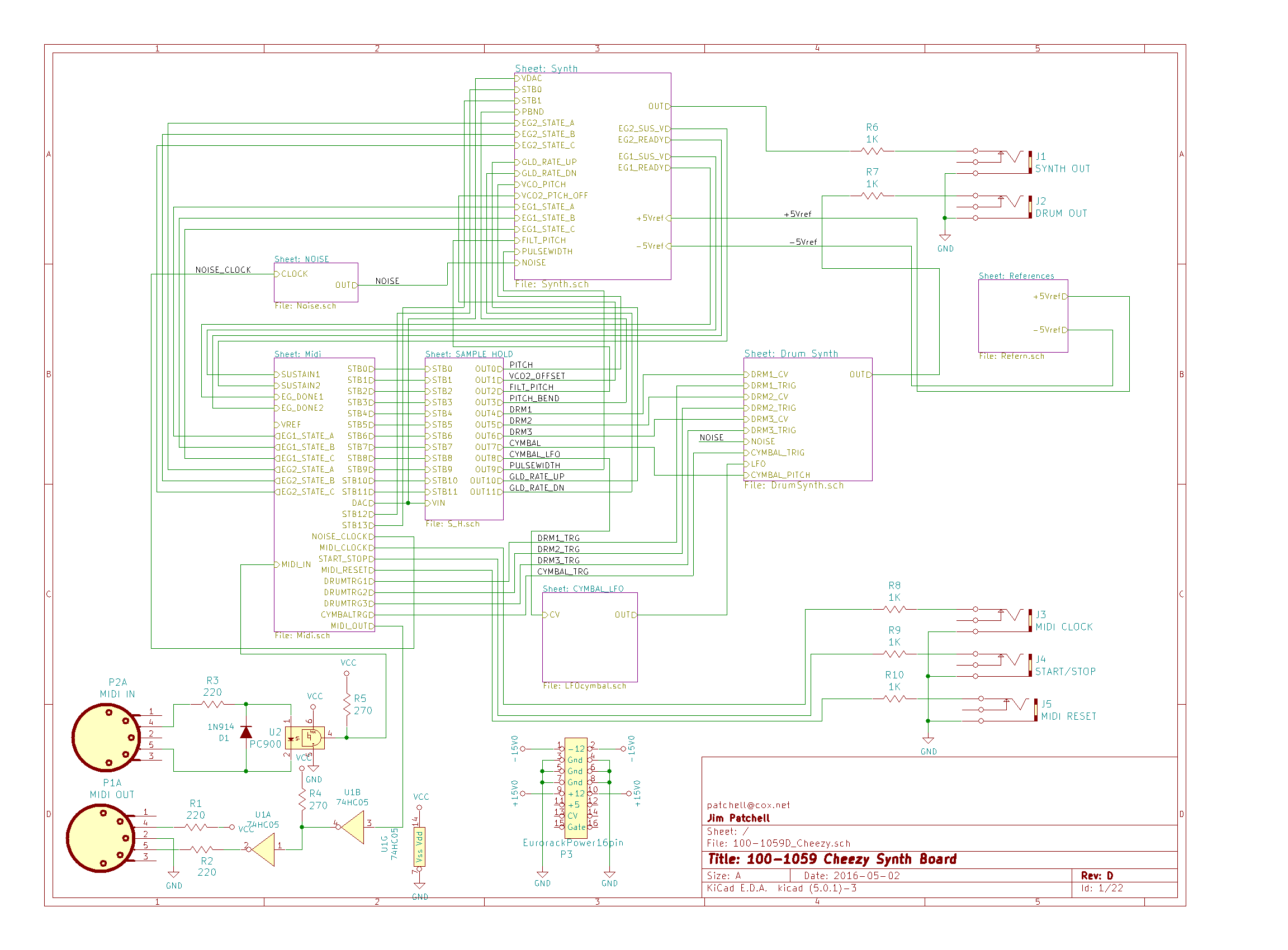
The schematic is not quite done yet, but it is done enough, I think, to
post. Keep in mind this is a minimalist implementation. The
schematic is only 32 pages long. Well, maybe it is not quite as
minimalist as I would have hoped, but I am afraid that this is about as
minimalist as I can get. The project also had a bit of feature
creep. After seeing the Korg Monotribe in action, I decided to
add some analog drums to the thing. I mean, what the heck.
The drums are sort of an expansion of the Paia drum oscilator
that you can find on their web page. The Cymbal was tough.
When I checked google to find out how other people implement
cymbals, I discovered that most everybody punted and used samples.
But this is supposed to be cheezy. So I opted for filtered
noise. I am using a ATxMega A3 processor on the board to do the
Midi, Sequencer and on board logic as well as interfacing for an at
this time undefined user interface. I am planning to use an I2C
LCD display, along with LEDs and push button switches.
Anyway,
hopefully I will soon get all the details filled in on the schematic.
Keep in mind, this was drawn by somebody that is legally blind.
If you do see something that looks real weird, let me know,
because I probably just didn't see it. But you will find a bunch
of places where there are no component values, no power supply
terminals, etc. I am going through the thing page by page filling
in those details.
Feb 7, 2012
Progress is slow. It looks like the schematic for the synth board
is just about done. It is generating a BOM and a NetList now.
And, I think I have just about most, if not all, of the details
filled in. I am still trying to locate parts for the board.
It is sort of silly, but connectors are proving to be difficult
for me to find. As of today, I have updated the schematic.
I will hopefully soon be able to post the ORCAD files for this.
Preliminary Schematic for a Cheezy Synth Module Board (updated May 14, 2012)
March 21, 2012
Progress has been slow on this project. I have been doing the PCB
layout now for quite a while. I am still in the phase where I am
placing parts on the board. This has always been the most
difficult part of a PC board project, but man, it is really tedious
now. While plaing the parts I have found several omissions
and boo-boos. These have been fixed. The schematic is still
not quite complete yet.
Also on the drawing
board is the PC board that will handle the user interface functions for
this board. That is still pretty much in the works, and will
probably get posted soon.
April 5, 2012
I have started laying out the voice card. This started nearly a
month ago, but I finally got all the parts placed and am now starting
to route the board.
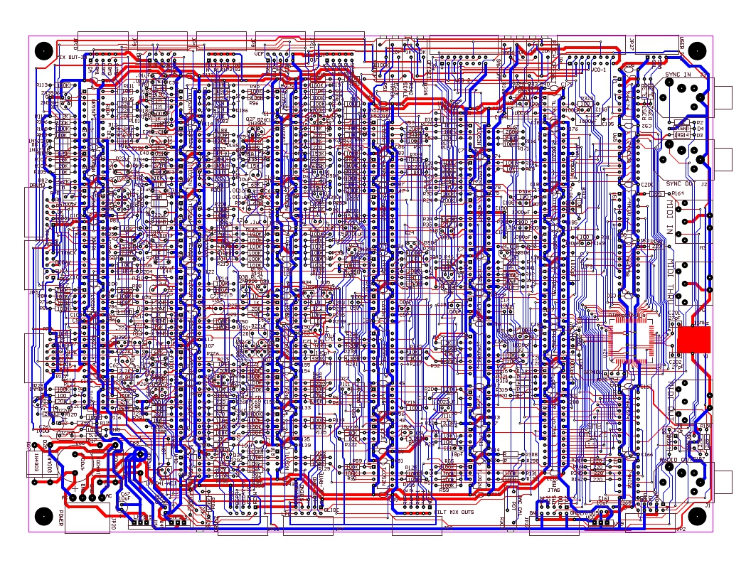
**UPDATE The above picture is pretty much the final version. Posted July 1, 2013
As
you can see, it is going to be sizable. 10x8 inches (80 square
inches). I will be updating this photo from time to time.
May 14, 2012
Well, I have changed my mind a bit. Originally, I was going to
use an ATxMegaA3 part for the cpu. I decided to keep the same
basic architecture across several projects, so, I have reverted back to
the ATmgea2561. Another reason is to potentially make this
project Arduino compatible. This will also allow me to add a
couple more control voltage outputs as well. The midi controller
is going to use my new library, so it is going to look a bit strange.
December 18, 2012
Well, I haven't changed my mind since March yet. I have almost
got all the componentws replaced on the board. I have posted the
latest schematic. I discovered last night that there was a twenty
pin part on the board that was doing next to nothing. It was the
address latch for the external memory bus. I made a slight change
to the circuit, and was able to eliminate that part. That
was a big help.
July 1, 2013
I am itching to get this done. Yesterday, I went through the
schematic and fixed all the problems I could find. There were a
few to say the least. Such as, Omitted a couple of resistors, a
couple of opamps had their inputs swapped, and a few signals were not
taken out to a connector. I have added a lot of stuff to the
silkscreen as well. Gonna sit on it again for a few days, while I
do other cleanup, such as checking pad sizes, and hole sizes.
October 16,. 2014
I
am still working on this project, but not at the rate I would like to.
I am also working on the NOOTA project right now, and I have
given that a higher priority. However, if I am stuck on the
NOOTA, I work a bit on this one. I am doing another redesign of
the board, AGAIN! And I am also analyzing the circuits so that
others will have an easier time making mods to my design. The
first circuit I am doing is the Twin T filters. The Twin T is not
an easy circuit to analyze. And I had to back off a bit and start
out with a special case for the twin T whiich is not actually very
useful for us. This is the case where R1=R2=R3/2 and C1 = C2 =
2C3. Now that I have that case done, I will work on the math for
when R3 and C3 are arbitrary. The analysis can be found here.
Anyway, here are the first file releases. This is an open source project.
Orcad 9.2 Schematic File
Protel 2.7 PCB file
Schematic file (PDF format)
All for now.