A New Synthesizer
Project
First Posted 11-23-2002
Updated April 5, 2012
Modular Synthesizer
Modular
Sequencer
Logic Module
Memory Module
Sequencer
Module
Updated Schematics
Updated 3-28-2004
You will find a
directory of schematics
here.
Modular
Sequencer
5-9-2004
This has been an ongoing project now for
several years. I am finally starting to get everything
designed. Originally, this was going to be a single 8U high
panel, but, it has sort of expanded into three panels now. Such
is the way of Feature Creep. I am probably going to be the only
one who will enjoy using this thing, because in order to make it you,
you must patch it. There are no default settings. Plus, in
order to patch it, you do have to understand at least the basics of
logic design. The system consists of a whole bunch of logic
primitives that can be connected together with bannana plugs.
One of the primitives, the Adder/Subtractor, is not
really so primitive. It is more like a four bit ALU. It has
three inputs that control the function of the outputs. Currently,
it performs the following 8 functions:
C=A+B
C=A-B
C=A
C=A xor B
C=A and B
C=A or B
C= 0000
C = 1111
The rest of the logic functions in the modules
consist of AND, OR, XOR gates, registers, JK flip flops, decoders,
shift registers.
In the Logic module there are 8 4 wide, 4 input,
AND-OR logic arrays. (See Below). These have programable
(with a switch) logic inversion of each input. This module should
come in handy.
There are also a couple of 8 bit DACS as well as one
8 bit ADC.
In the Memory module, there is a 16x8 pattern
generator (a ROM that uses toggle switches as the memory element), as
well as a 2048 x 8 ram module that can be loaded via RS-232.
Since some of the same PC boards are used behind
multiple panels, here is a list of the current schematics and PC board
layouts.
Pot Selector
Adder Subtractor/Register
Dual 4 input AND/4 wide Or
Misc Logic Board I
Pictures
More to come....
I am calling this
module a memory module. A picture of the module can be found
here. Again, just a drawing of the
front panel. Hopefully, I will start construction soon. The
main feature you will note on the panel is the Pattern Generator.
This is a 16x8 array of toggle switches. The ABCD inputs select
one row of switches, and their state can be read out on D[0..7].
The second most prominent features are the RAM modules. These are
2048 x 8 bit ram modules that can be loaded via an RS232 port. I
was debating if I should use MIDI to do this, but in the end, decided
on RS232....I might change my mind before I start constructing, who
knows. There are also a pair of DACs that can be used to provide
control voltages to other analog synth modules.
The module is rounded out by what will hopefully be
some useful random logic blocks. There are four Adders (really
more like a mini ALU) that can perform ADD, SUB,
A->OUT,XOR,AND,OR,0->OUT,1->OUT functions, and there are four
registers, which in combination with the Adders can be used to make
counters and what not. There are a pair of 2 to 4 decoders, and a
pair of And/Or/Xor gates.
A document of the
module can be found
here, it includes
schematic as well as the front panel. As of today, nothing has
been
fabricated and I am probably going to change a few things before I
start building. Hopefully
Most of the panel space is occupied by the 4 input,
4 wide AND-OR modules. There are 8 of them. Each of the 16
inputs has a toggle switch associated with it. This toggle switch
determines if the input is inverted or non-inverted. While these
logic units are not very deep, when compared with a macro cell in say a
22V10, they should prove to be quite flexible.
The next submodule are the adders. These are 4
bit Adder/Subtractors. There is an input that controls whether
they add or subtract. There are also Carry In (CI) and Carry Out
(CO) jacks so that the adders can be cascaded. Adder/Subtractors
are used primarily to implement counters, using the Register Modules.
The Register submodule is a 4 bit D type flip-flop
register. It has a clock input (CLK) that is positive edge
triggered and a reset input (RST) which is active high and resets the
register to 0000.
There are a pair of JK flip flops that can be used
to extend the operation of sequencers. JK flip flops are the most
versitile. There is a switch on the K input to make that input
either Active High or Acitive Low. If it is Active low, you can
connect the J and K inputs together and make a D flip flop. If
you set the switch to active high, you get a T flip flop when you
connect the J and K inputs together.
Another module is an 8 bit A/D converter. It
has a voltage input, that can range from 0 to 5 volts, or there
abouts. There is a clock input ON the panel for the A/D
converter, but, that will be removed..(I found no way to do this
nicely). There is a signal for starting the convert, and another
to indicate when it is done.
And another module is a shift register module.
These can be useful for generating pseudo random sequences.
Update 7-20-2004
Got the front panel yesterday, and I spent the day
putting the part in it...I was off because I had a minor surgical
proceedure....and I was supposed to be taking it easy....
Anyway, here is the
photo.....
Update 8-15-2004
Started to wire this panel up this weekend.
Got the And-Or matrix wired, took about 12 hours so far this weekend.
Anyway, here are the
photos.
This is what most of you will actually
recognize as a sequencer, since, this module has the pot knobs on
it. A picture of the front panel can be found
here.
This module consists of a selection of sub modules
that can be patched together to create sequencers. Most of the
panel space is occupied by the Pot Multiplexors. The inputs A, B,
C are used to select one of the 8 pots. The IN jack can be used
to add another control voltage to the default 5 volts that is built
in. So if you apply 5 volts to the IN jack, that will be added to
the 5 volts that is already there, making for 10 volts. In this
particular case, the knobs will adjust the voltage on the OUT jack from
0 to +10 volts, rather than the default 0 to +5.
One thing should be noted. The
sections that contain the pots only have logic inputs that select the
pot. To make it work like a traditional sequencer, you can use
all of the logic primitives that are also on the panel
(Adder/subtractor, 4 bit registers, XOR, JK flip flops, decoders)
to create counters and logic sequencers. I did this because it
allows me to have ultimate flexibility in how the system is
configured. Although, this will make for a mass of patch
cords...but, I like chaos.
The pot sections have an output and an
input. If you connect a voltage into the input jack, then the
output will be that voltage attenuated by the selected pot.
The decoder module is handy to select the various
pot multiplexors. There are 3 in 8 out and 2 in 4 out.
These decoders are active high. Only one output will go high for
each input combination.
There is also a midi interface that
will provide for START/STOP (same jack), and RESET functions, as well
as RAW midi clock and midi clock divided by 7 different constants.
Modular
Analog Synthesizer
9-18-2004
Updated April 5, 2012
Firmware Update in the Works
April 5, 2012
Well, this is revolting. I thought I had completed the firmware
for this thing some 8 years ago. I went to use some of the
features I thought were in the synth, and, HEY! they weren't there.
Surprise!
Now originally I wrote the firmware to compile with the Image Craft C
compiler. I no longer own that piece of....software, so adding
the things that were missing means I need to rewrite the code so I can
compile it with the GNU tool chain that I now use. Still, kind of
a bummer. This time, I am going to make sure I finish the job.
I had to borrow an In Circuit Programmer since I seem to have
misplaced mine. I might also try to add support for the external
ram that is on the board while I am at it, if I can find the RAM chips.
A new Chassis
sometime in 2004
Well, here it is
almost a year later, and I finally got around to making the chassis for
the Modular Synthesizer. I was going to use a Bud 17x14x3 inch
box, but, it was too small in two dimensions by about 1/8 of an
inch. So, I got my rear in gear, and purchased some sheet metal
to use with the tools I purchased last year when I was up at the PNW
SDIY meet (purchased a Grizzly Shear and Corner Notcher).
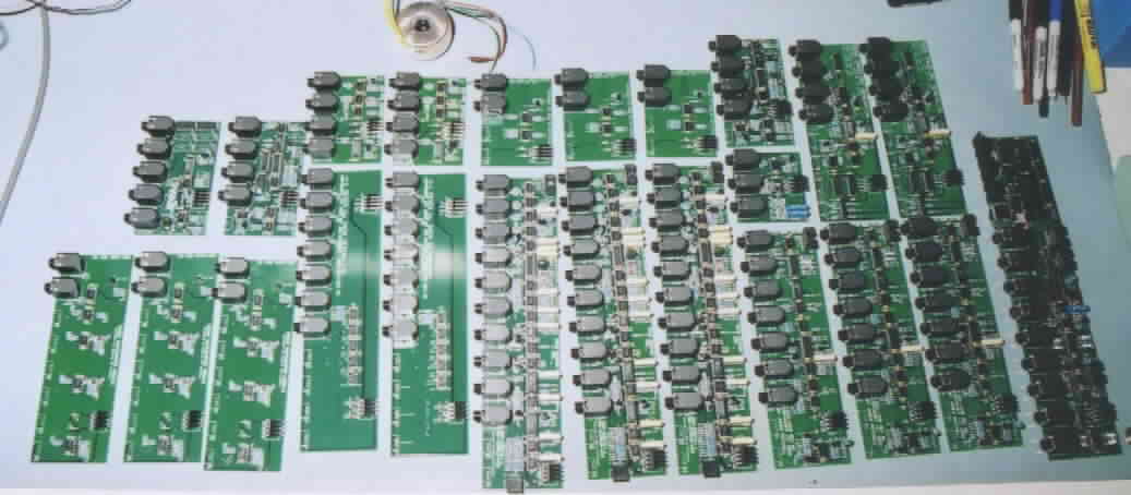
So, here is a picture of the
Parts.
Still not really done at this time...more updates to
follow...I hope.
12-16-2003
Latest Updates
Well, I am
still pretty happy with this synthesizer. I worked on the
firmware a bit more. For those who
may be following this, the uController on the Midi->CV converter is
a AT90S8515. I will be changing this to a MEGA8515 in January of
2004...I hope. The MEGA part is capable of 16MHz and it has a
multiply instruction.
The VCO's sure do seem to be about as rock solid as
you can get. While I have not actually checked to see what their
scale factor is, all three oscilators are tracking in their
tuning. These are the first oscilators I have ever had do
this. In fact, I am suspecting that they are even more stable
than the CEM3340s that I used to use. I will have to fire up a
synth that used these parts to find out if that is indeed true or not.
I am also hoping to get a Real Time Operating system
running on the CPU. This is probably not going to be easy.
I could use Salvo, but, I am too cheap to pay even that low price for a
Real Time Operating System. I am planning to port the RTOS I
wrote for the 68000 over to the AVR.
11-30-2003
Well, I have pretty
much got this synth completed, in that I can use it to play a
tune. I met pretty much all of my goals. The Recuring Labor
on this synth came in at about 40 hours, which was my goal. It
did take a bit more time to actually build this first one, because
there were a few boo-boos on some of the cards. All of them were
minor, but it still takes some time. I still have to finish the
code for the Midi->CV converter yet. But that is about 80%
complete.
I am very pleased with the way this project turned
out. It is clean, and it sound, in my opinion at least, real
good. I still have to build a box to go around it all. In
order to do this, I need to set up the sheet metal tools I purchased
during the summer.
So to start off with, here is a 15 second sound
sample I made from the synth....
MP3 Sound Sample
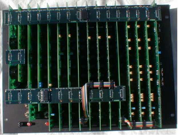
And here are some pictures of the assembled unit.
Rear of panel (PC boards and
wiring)....
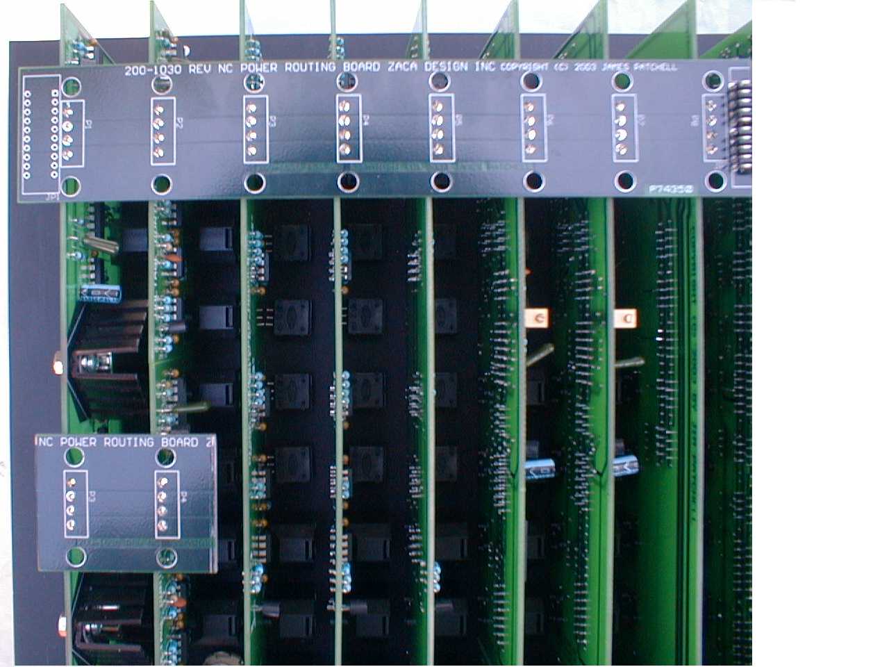
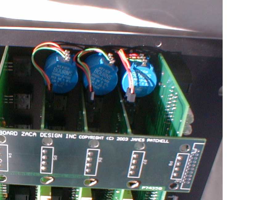
Closeup of Rear
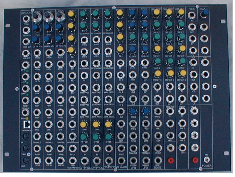
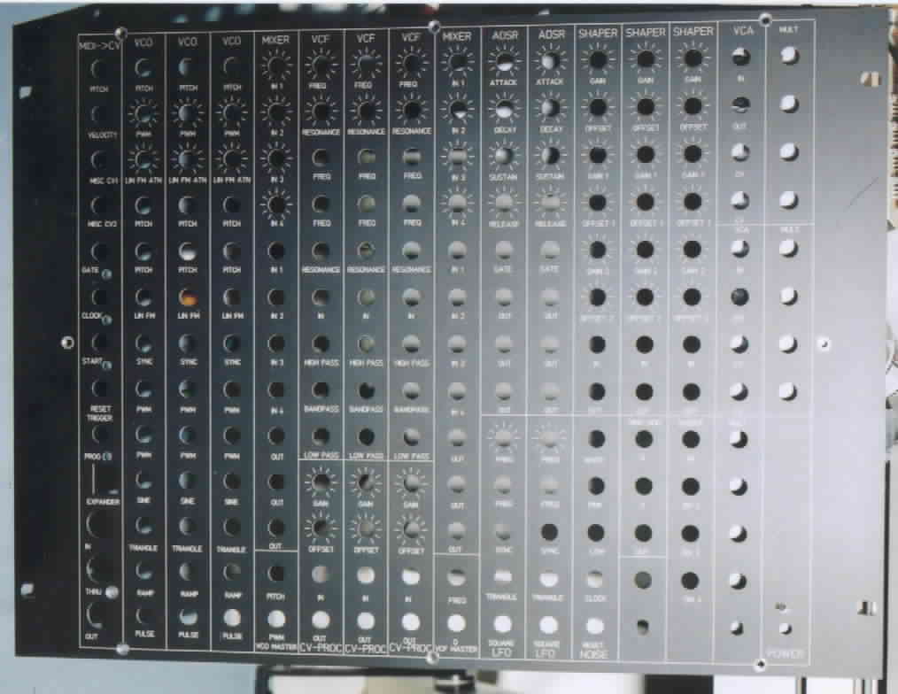
Front of panel
This is all of the point to
point wiring
Side view of rear
9-2-2003
Here it is, September of 2003, almost a
whole year since I started this project. One of the goals was to
design a synthesizer I could build in a reasonable amount of
time. So far, it looks like I am going to meet that. I have
about 20 hours of work into the build of this project, and a good
amount of the work is finished. You can see the photos below for
the details. I do have to build a jig yet to solder the panel
pots to the boards, but, that is just a detail.
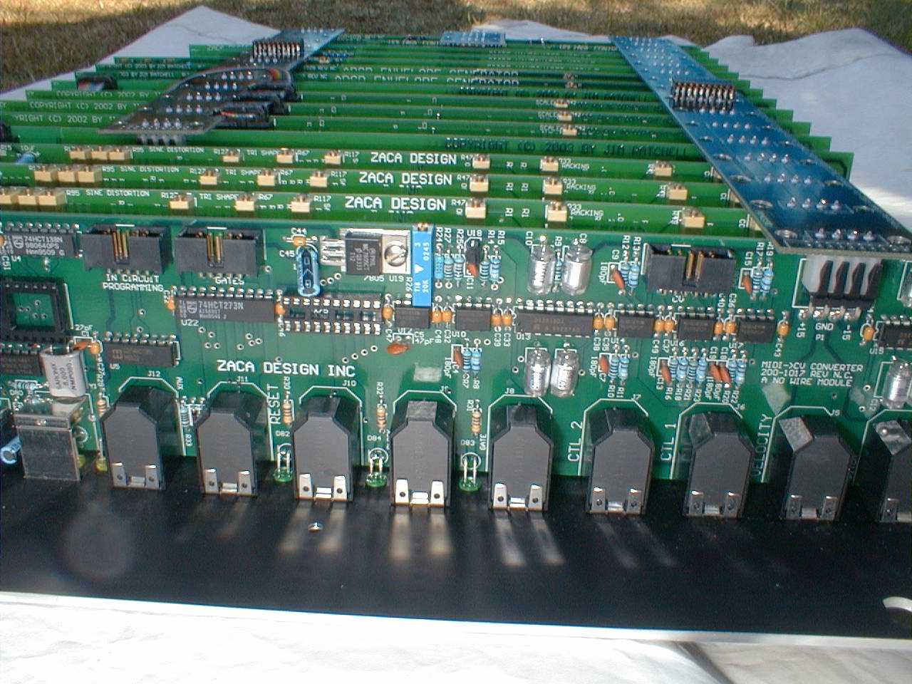
In the photo of the boards, you can see pictures of the Midi->CV
converter, 3 VCOs, 3 Multimode VCFs, 2 ADSRs, 2 VCAs, 3 Diode wave
shappers, 3 CV processors (gain/offset), 1 noise generator (32 bit), 2
LFOs, and 2 4in/1out mixers.
Picture of PC Boards
Picture of Front Panel
Picture of "Killer Bees"
One of the problems I have been experiencing with
my latest synthesizer projects is the amount of time it takes to do the
front panel wiring. There are several reasons for this. The
biggest one is I just can't see as well as I did about 20 years ago,
and
that really hampers things. So of course the big question in,
what
can be done to build a modular synthesizer module without having to do
a lot of tedious wiring. Well, mounting the jacks and the pots on
the printed wiring board is of course one answer. I discovered
that
this was a lot easier said than done. The jacks were fairly
easy.
I am using the Switchcraft SC112 phone jacks. Pots, on the other
hand, are a big problem. A problem that is only partially solved,
at this time. Currently, I am using the Vishay Model 248
pots.
These are a bit pricey. But, the feel good. There is sort
of
a problem in mounting them to the board, in that the ceter of the pot
does
not line up anywhere close to the center line of the Jacks. I
plan
to solve this by making a jig to solder the pots in the board
with.
I would first mount the Jacks, the mount the board in the jig using the
jacks to support the board, and then solder the pots.
Also, this will be the first Synth project that
will
use a panel made by Schaeffer. It will cost about $400 to get
this
panel made (I use a 14" x 19" panel), but they look great, and besides,
it takes me somewhere between 10 to 20 hours to make a panel by
hand.
And these days, finding 20 hours of spare time is getting more
difficult.
The rest of the chassis will be a 14" x 17" x 3" aluminum Bud chassis
box.
I put pem nuts in the lip and then screw the front panel to the
box.
Looks pretty clean. The first module I did this with was the
prototype
of the Mikado. The only problem I have not solved is where to put
the power supply...
The PC boards are 2.75 inches by however long
they
have to be to accomodate the number of jacks and pots the module
needs.
The Midi->CV converter actually got a couple of jacks added to it
because
I had to stretch the PC board out an extra two inches to accomodate the
components.
This VCO uses the
temperature
compensating circuit that several others (especially Jurgen Haible) and
myself were able to come up with. The core of the VCO is pretty
much
a standard sawtooth VCO, often refered to as an ASM-1 type VCO.
Actually,
this VCO was originally concocted by Terry Michaels and was published
in
Electronotes. The VCO also features a fairly sophisticated
Triangle
to Sine converter using a CA3280. Also, the VCO has an onboard
driver
for powering the main Frequency Adjustment control. It is
intended
that a multi turn pot be used here. The onboard driver has a gain
control so that it is posible to set the VCO up so that 1 turn of the
pot
equals one octave exactly. There is also an auxiliary connector
on
the VCO so that it would be posible to have a master pitch adjustment
knob
as well as a master PW knob.
This is a fairly standard Voltage Controlled
State
Variable Filter (Multimode). It features a temperature
compensation
circuit similar to the VCO. Limiting is accomplished using a pair
of LEDs. The LEDs can poke through the front panel so that you
can
get an idea of when the filter is going into limit. This filter
also
features voltage controlled Q control as well.
This circuit is by far the simplest of them
all.
It has 1 input and 1 output. You plug the output of a module into
the input, and you can vary the gain, from -1 to +1, as well as the
offset,
from -10 volts to + 10 volts. Very handy for modifing the output
of an ADSR.
Similar to the simple processor, except, you can
set two break points where you want the gain of the module to
change.
In this way, you can shape an incoming signal if many ways. This
module was primarily intended to be used with the filters to create
phonemes.
The noise generator I chose for this projects is
a 32 bit maximum lenth shift register type. It has an internal
clock,
but, this can be over ridden by using the clock input to supply it with
another source. This is handy for generating random sequences of
notes. Also, there is a reset input that will set the shift
register
back to its initial state so that the sequences can always be the same
if you wish. It would have been cool if it were posible to set
the
"seed" that it reset back to, but, that would have been too
complicated.
This modules uses an Atmel AT90S8515 micro
controller
(AVR). The board has an ISP connector on it so in therory, if you
wanted to do some hacking, you can program this thing yourself.
Other
features of the board include 8 control voltages. Four come out
on
jacks, the other four are on an aux connector on the board. The
standard
firmware also support Midi Clock, RESET, and START/STOP.
Please Note, as of 11-23-02, I have not checked
this
schematic for acuracy. The Midi connectors could be backwards.
This is the quantizer out of the Mikado. I
am not sure if I am going to include this in the synthesizer of
not.
Because of the way I designed the Noise generator, I probably don't
need
this module.
This vca is a little bit different...I use
an LM13700 instead of my favorite CA3280E. This version has a
very low distortion. The Jury is still out on weather this is a
better choice.