And now for some pictures
of
home built synthesizers
Page Last Updated 04-27-2003
JP II
And now for some pictures
of
home built synthesizers
Page Last Updated 04-27-2003
JP II
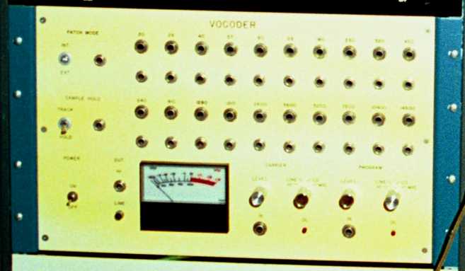
This is a vocoder I built. I built it without ever having seen a vocoder. I heard one at an electronic music concert at UCSB around 1980, and did my best. Hopefully, I will soon rework this beast to make it work a little better. It is constructed all on PCB's, far too many. The boards were all hand taped, and not as dense as they could have been.
Latest Update...I have it working again, in fact, just today (4-27-2003). Here is an MP3 Sample.
JP I
JP III
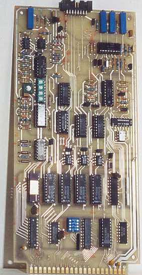
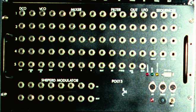
This board is one of the VCO boards for the JP III
synthesizer.
It talks to a uP bus that is 6500/6800 compatible (it was originally
intended
to be used with a 6502 uP, but later, decided to switch to a
68008).
There are five DACs, one 12 bit DAC and 4 8 bit dacs. The 12 bit
dac is for setting the pitch of the of the VCO. Another 8 bit dac
is used for tuning the scale of the 12 bit DAC, if that is
needed.
Another DAC is used for setting the Pulse Width, and the other two dacs
control control voltage attenuators. There is also an 8 bit latch
for controlling various functions, such as control voltage inversion,
wave
form select, etc. The VCO is a CEM3340. A CA3280 is used to
shape the triangle into a sine wave.
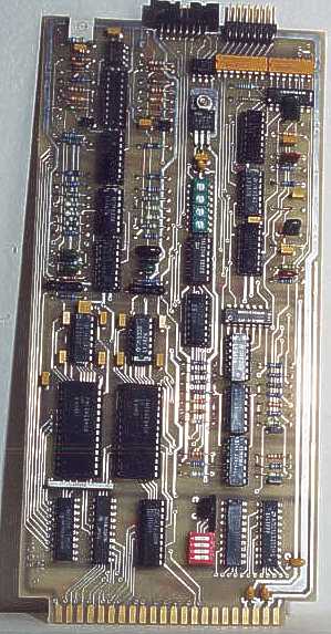
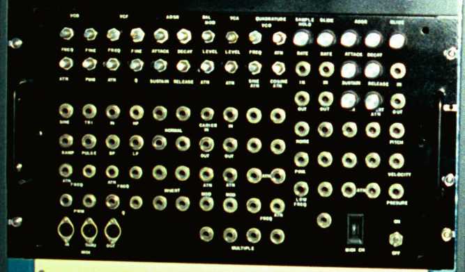
This is the VCF/VCA board from the JP III
synthesizer. It also has a bus that is compatible with the
6502/6800
uP. This board features two state variable filters implemented
with
a CEM3350. The filter can be connected either in series or in
parallel.
The two ADSRs are implemented with a pair of CEM3310's, the VCA is a
CEM3330
and the four control voltage attenuators are implemented with a pair of
CEM3360s. There is an 8 bit latch for controlling various
functions
on the board, such as connection of the VCF, control voltage inversion,
etc. Both of these boards were done around 1984.
This was going to be my midi merger. It was started in about 1987. It was never finished. Mostly because I did not yet have some of the skills I really needed to do so. I have plans now to finish this. It is based on a 68008. One of the reasons it failed was because I still had not purchase a good compiler (that would be in 1988). I was attempting to use the Mark Williams C compiler for the Atari ST to write the code. That proved less than successful. I lost interest in this before the above synth. But at least I did get the above synth ported to the good compiler before I gave up. When I start up the Midi merger again, I plan on making the UARTs in a Xilinx Gate array and using a real time operating system that I wrote.
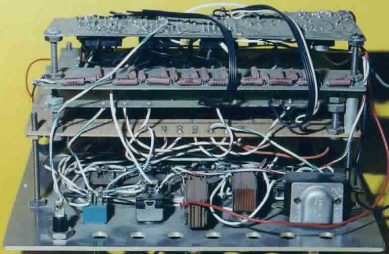
This is the MOSFET power amp I designed and built. While it still has negative feedback, it only has 20dB of negative feedback. It also has a 1MHz bandwidth (treble anyone?). It puts out about 80 watt's per channel. It has a dual JFET input (U235), a mosfet second stage (sorry, I don't remember which one, but it is a P-MOSFET). The output stage is made up of of two IRF120 's and a IRFD9120 and Two IRF9130's and a IRFD110 connected up so that the output stage has a gain of 5, if I remember correctly. Temperature compensation is a real problem with Mosfets. This amplifier has a slight thermal oscillation but it is not noticeable (by me). A newer circuit I am working on doesn't seem to have this problem and soon hope to start implementing it.
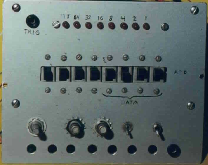
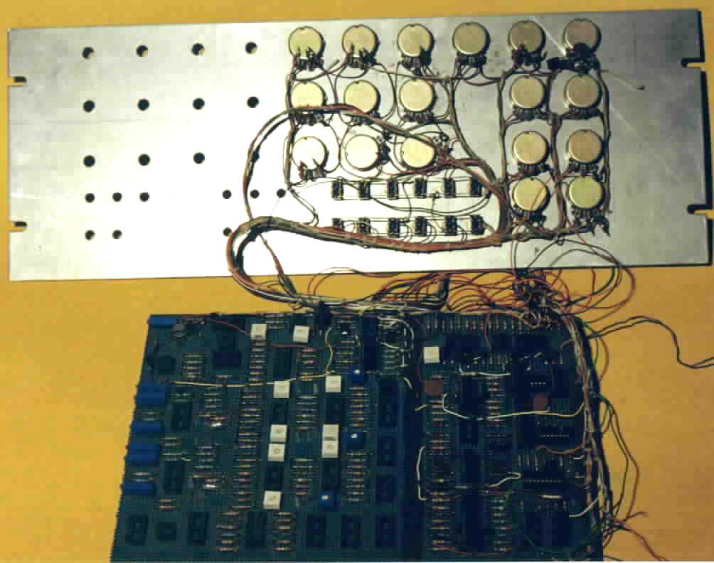
This is a very early work. It dates to about 1975. I was still in collage at the time, and it was built out of whatever happened to be around. What is it? Why, it is a sequencer. I don't remember exactly how it works, but, it was based around 4 256x1 ram chips (those were very pricey back in 1975). The data was stored as 3 nibbles, I think. The first two made up an 8 bit word that went to a DAC, and the third was loaded into a counter, to set the tempo. If you notice from the picture above, there is a board with a bunch of 1% resistors. This was an R-2R ladder (Dacs were very expensive). The boards were all etched copper clad, this back when I still did that kind of stuff. It was cumbersome to use, but I had a lot of fun with it.
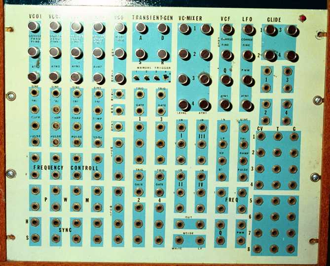
This is not a very good picture. But, this is a mono synth I started to build at about the time when I gave up DIY back around 1990. It is half done. The only thing left to be built are the two VCO's. This thing was based on the CEM chips, 2xCEM3340, CEM3350, CEM3310, and CEM3330.
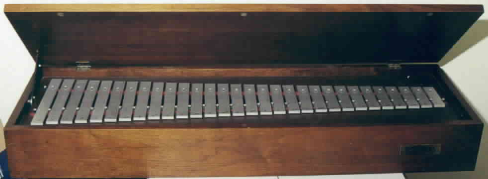
This is a Rogers Glockenspiel that I converted over to midi. It used to be part of a Rogers Organ, but, the organ was scrapped, but I managed to get this.
Link to technical data for Glockenspiel
As of January 11, 2003, the current status of the
Glockenspiel is that all the note now work. There were two that
did
not fire because they were stuck in the decaying foam that Rogers used
to keep the plungers from making noise when they came back down (they
just
hit wood). A third note did not work because of a broken
wire.
Taking this thing apart was not at all fun. I needed to replace
that
decaying foam because it was pretty noisey every time you played a
not.
I replaced the foam with felt, which while it is a whole lot better,
still
makes kind of a thump when the note is played. Also, to replace
the
foam, I had to remove the circuit board that held the solinoids.
To keep manufacturing cost down, it was just stapeled to the
frame...grrr.
I had to very carefully pry the stapels out of the phenolic
board.
The phenolic was pretty old and brittle. But hey, now you can
play
tunes.