The Teletrac Spinstand
First Posted June 7, 2004
Updated July 31, 2013
This is the spinstand project I worked on when I was
at Teletrac. What you see here are the prototypes for the
controller and the spinstand. I did not really have much to do
with the spinstand, as that was mostly a mechanical engineering
job. But, I did design the spindle controller.
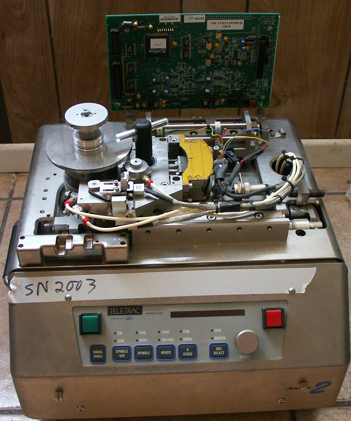
The thing was pretty beat up when this picture was
taken. But it does work. The bearings in the rotary
actuator were shot (the rotary actuator is connected to the black peice
of plastic with the clear rod sticking through it...that was there so I
could hold onto the motor when turning on the control loop when I
needed to debug PID firmware...if there was a bug, it could damage the
encoder on the motor).
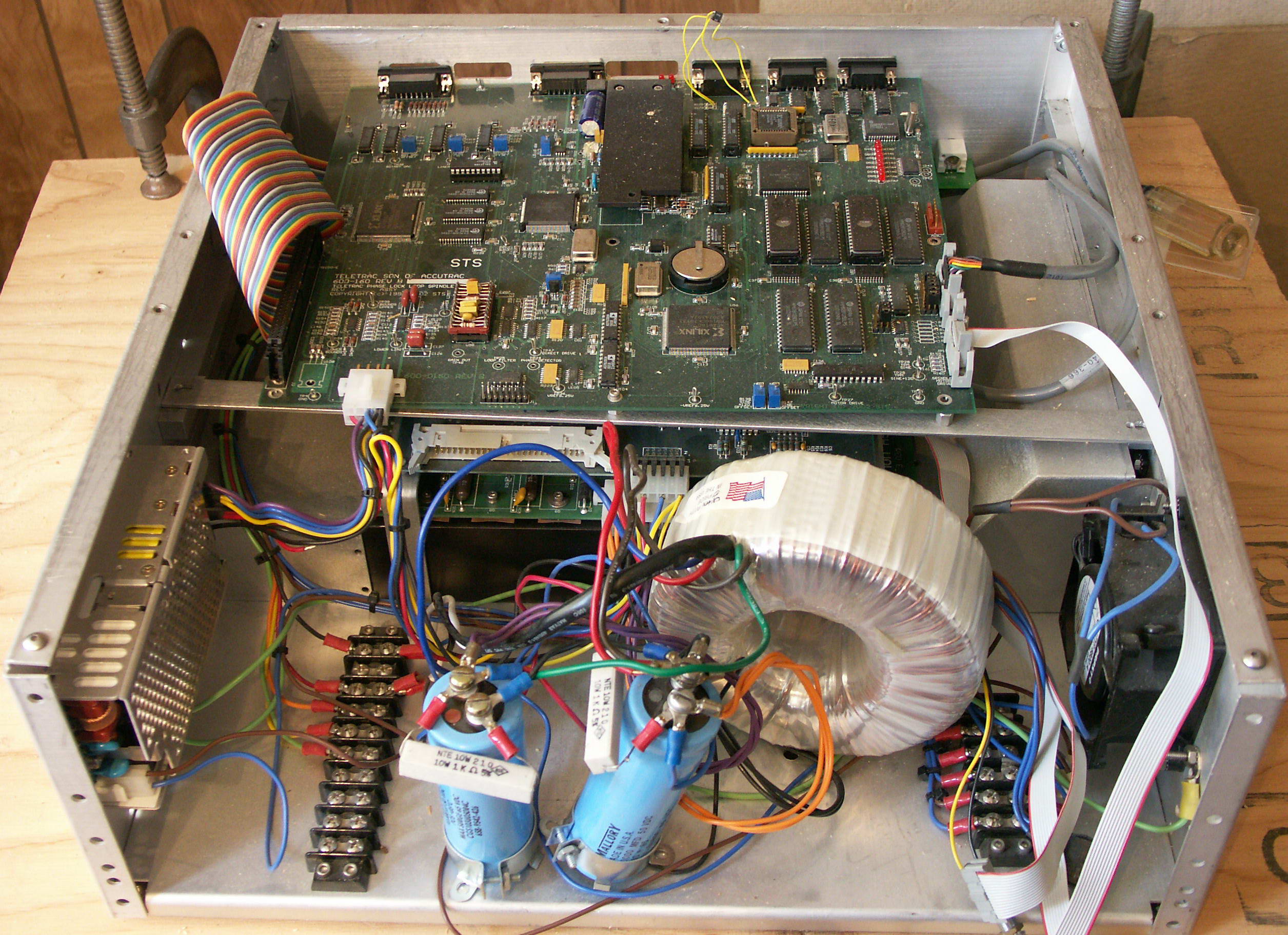
This is the spindle controller. The torroid
transformer provides the power spindle motor amplifier, which is down
below the main board. The main board gets it power form the
little switcher on the left. The big wide ribbon cable comes from
a Micro-E processing board that converts the output of the Micro-E
encoder into a 32 bit word. The encoder had a resolution of about
1 micro degree, and the controller could control the position to about
+/- 0.5 micro degrees, which is pretty increadible, actually.
On the main board, on the right, is the master
controller (a 68000), on the left of the board is the motion controller
DSP (56002), and in the front left, is a Xilinx Gate array that was the
spindle controller.
July 31, 2013
For those who are interested, this is the document I made that has all
of the schematics for everything I did in the system. It includes
the spindle controller board, gate array schematics, pld equations, DSP
code, 68K code, and the windows program used to verify operation.
Spin Stand Documentation