Blackmer
Synth Module Board
The NOOTA
(BMSMB)
First
Posted March 11, 2012
Changed Completely on July 18,2014
Updated September 2, 2014
Who rocks the scene with sound that's clean
It has the bass to shake your face
Filters so lean they really scream
Everybody knows its Noota
The best synth yet to give or get
The DJs will all want to try
The hit of the day when you are ready to play
Everybody knows its Noota
Its Noota, Its Noota
For fun the best of the synths
Its Noota, Its Noota
The favorite of girls and boys.
Everybody wants a Noota
Get Yourself a Noota
(sung to the slinky song tune)
September 2, 2014
Well,
I have had a minor setback. And it has to do with the VCO.
I am not sure why, but, the tempco of the gain of a Blackmer VCO
changes with gain. So, as it turns out, you need to figure out
what control voltage is required in order to exactly compensate for the
tempco of the VCO. The changes to the circuit are rather minor.
I was originally changing the scale factor by adjusting the gain
of the BMVCA that provides the temperature compensation.
This, of course, just won't work. The gain of the
BMVCA must remain fixed. So, I moved the tuning pot over to the
base of the transistor in the exponential circuit..
Another
setback which is related, has to do with ORCAD. I need to revise
the schematic. I always keep a copy of past mistakes, because you
never know when you are going to need it. This is really the
first schematic I have done, that became a PC board that uses the Synth
Blocks library I created. These are little circuit blocks that
are handy for making synthesizer modules. Well, as it turns out,
when I make a copy of a schematic that uses these blocks, all of the
reference designators of the components in those blocks gets
reset. Not good. I will either have to re lay out the
board, or pains takenly manual fix all of the reference designators by
hand. Neither option apeelling to me. So, I am working a
bit with orcad to see if I can figure out how to correct this problem.
Otherwise, I will go back to doing schematics the boring way.
August 2, 2014
I did
some checking on prices today. The NOOTA board would
probably sell for the neighborhood of $30 (bare) and the 100-1071 quad
pot board would probably sell for about $35 -> $40 for a set of six
boards. But this is getting just a head of myself a bit.
Before any orders can be taken, I need to get the thing to work
first.
August 1, 2014
I am just about ready to start making CAM files. But here is what I need to do first.
1.
Sell a bunch of stuff on EBAY. I am liguidating my model
railroad stuff since it is sort of useless to me now. This will
raise the necessary funds needed to get the PC boards fabricated.
2.
Before I send the artwork out, I would like to test the VCA circuit.
This means I need to build a breadboard. Not something that
is easy for me to do.
3. Do a panel layout.
After I
do get boards back and build up the first one I will decide if any of
this had any merit, or was it just a big waste of time.
And as soon as possible, I will get all the files posted. After all, this is supposed to be an open source project.
July 31, 2014
So,
as of today, the board has been completely routed. There are
still a couple of minor things I need to do to the artwork before it is
ready for CAM generation. I also want to verify the
performance
of the Blackmer Cell that I am using. Control feed through,
of
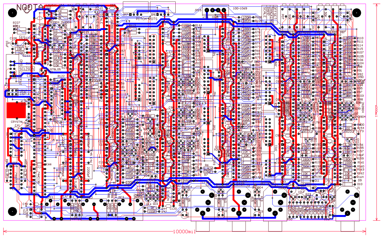
course, is a major concern.. I also need to go through and
calculate the values of the unknown parts as well. Here is a
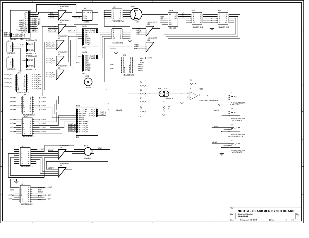
photo of the PC Board as it stands today. Also, the schematic
PDF
has been updated as well. See Below.
Now
as it turns out, this is not all I did today. I designed this
board to use some auxiliary boards that hold the control pots.
These are not needed, but, for those of us who are challenged
doing popint to point wiring, these will help make the assembly a lot
faster and easier. If you look on the schematic, you will
notice
that many of the connectors are labled with the part number 500-1071.
This is a quad pot board that also has the option for 4 LEDs
as
well. Here is a picture of the board.
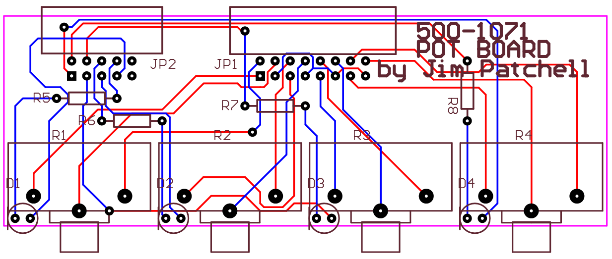
And this schematic can be found here.
I can't remember how many of these will be needed, but it is several,
OK, well, I just checked, it is 6. There are 8 connectors labled
with 500-1071, but the two boards for the Envelope generators have two
cables going to them, one for the pots, and one for the LEDs..
The
other board has 5 pots on it for the 5:1 mixer. Only one of
these
is needed, although, you could also use one with the 3:1 mix at the VCA.
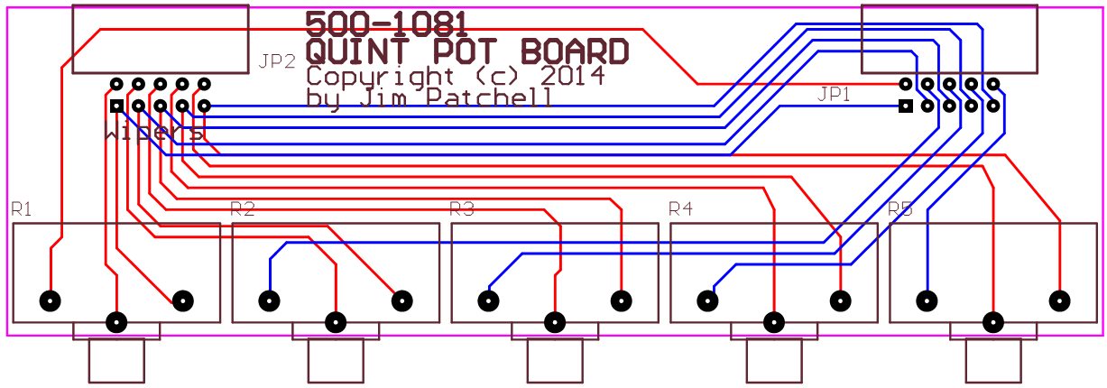
And the schematic can be found here.
July 23, 2014
Well,
ran into a little bad luck. As I was placing the parts on the
board, I discovered a serious problem with the netlist. Try
as I
might, I was not able to fix it in a way that would preserve what I had
done. In order to find the problems, I had to
re-annotate,
which ruined what I had done. On the good side, this will
give me
a fresh start on placing parts, and hopefully I will be able to squeeze
them in a bit tighter. At the density I was placing them,
they
would have never all fit on the 6x9 board. Anyway, I
have at least updated the schematic PDF file to reflect recent changes.
July 19, 2014
Schematic
is STILL not done, but it has been updated considerably, and is also
two more pages long. See below to download the PDF of the
schematic. However, I have gotten it to netlist and
as well
as load the netlist into Protel without any errors. So that
is
something at elast. There are currently about 480 components
on
the board. Man, that is a lot to have to place on a PC board.
And even worse, to solder. Not really sure how, but
I vow I
will get this one to a OPC board.; It is just so different, I
have to do it.
July 18, 2014
When I first started this project back in 2012, my foals were a lot
different. Well, not too different, actually, but I was
willing
to include a couple of OTAs that were used in the VCOs for temperature
compensation. But, I continue to learn. And I
decided that
why not try and also use the Blackmer Cell to temperature compensate
the VCOs as well. So, thus the NOOTA (No OTA) Synth Module
Board
was born. So, in this project, you will not find a single
OTA,
anywhere. So, this is a complete redesign. The
structure of
the synth is fairly cliche. And it is also fairly simple.
I
like to think of it as a NOOTA'd version of the ASM-1 synth board.
So
what do you need to build this circuit? The only expensive
chip
is the MAX551 DAC chip. It comes in at about $13.
The next
most expensive chip is the ATmega328 micro controller,
Everything
else is pretty run of the mill, TL052, DG201, some HC logic, and a
bunch of 2N3904 and 2N3906 transistors.
I chose the ATmega328
partly because of the fact that it is an popular Arduino processor.
Even though I am not going to use it that way, if you are
enterprising enough I am sure you can figure out how to get it into
that environment.
This
is an open source project. So, as files become ready, I will
post
them. The schematic is still not done yet, it needs to be
gone
over and all the little details filled in, and then I can lay it out.
I suspect this will be about 8" x 6".
Another
thing I have
to work out is a block to put the transistors into for the BM cell and
Expo transistors (a total of 7) as all of these need to thermally track
each other in order for the temperature compensation to work.
PDF of above schematic.
Orcad 9.2 Library of
Circuit Modules. I sort of think of this as being a Synth
BLOCKS library.
Features of this synthesizer include:
1.
Microprocessor controlled envelope generators. The core of
the
envelope generators is basically the same as the glide circuit.
The micro controller supplies a voltage level and a time
constant
control to the glide circuit depending on the current GATE and the past
history of the envelope output. The control voltages are
supplied
by having the micro controller read a set of four pots which set the
Attack time, Decay Time, Sustain Level and the Release Time.
2.
All of the transconductance functions are done by Blackmer
Log-Antilog multipliers. I decided to use a semi discrete
version
rather than using something like the THAT Blackmer VCA. I am
trying to get away from using the odd specialized chip here and there.
I really miss the CA3280. And learning to do without will
make me
stronger. Some chips you just have to use. For
instance, if
the ATmega2561 goes obsolete, it is not too big a deal. There
will always be some other type of micro controller to take its place.

Noota Blackmer Synth Module Board by James Patchell is licensed under a Creative Commons Attribution 4.0 International License.